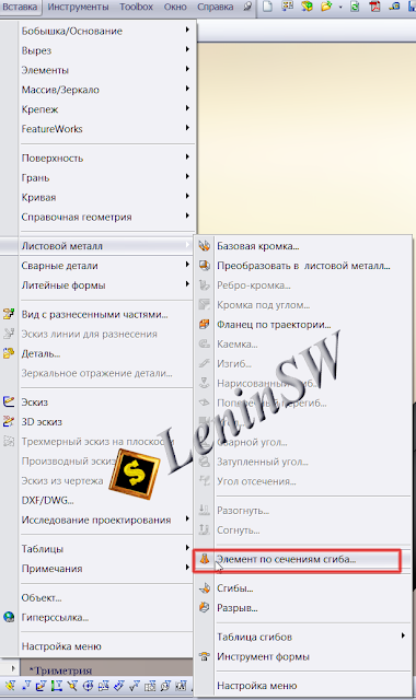
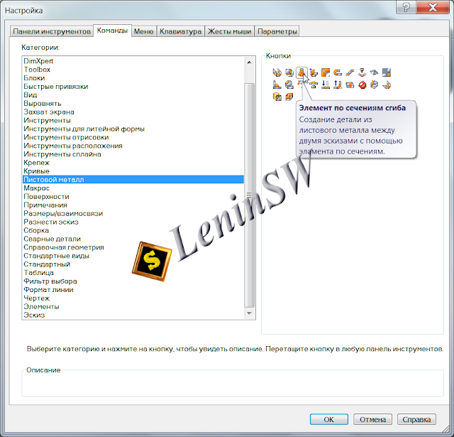
It is necessary to make the transition from a round tube to a square of sheet metal. Let us consider the principle of constructing such scans from sheet metal. In order to get a sweep of it you need to build it using the tool "Element by the bend cross-sections". It is located in the Sheet Metal toolbar, in the Insert menu - Sheet Metal, on the Sheet Metal tab, or you can take it to the right place when setting up the Solidworks interface.
 |
| "Элемент по сечению сгиба" в меню "Вставка" |
The construction scheme is as follows:
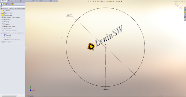
We construct a sketch of a circular non-closed section, the gap is necessary to obtain a sweep. The gap must be dimensioned (generally a fully defined sketch reduces the probability of error), you can make 1mm or less.
We create a plane on which the profile of the second section will be located and on it we draw an open quadratic profile, with a gap. Gaps can be linked either by an equation or by using separated values (more conveniently).
It is necessary to round the corners of the square section, otherwise Solidworks will give an error.
After that using the Solidworks tool "Element for the bend cross sections", create a transition from the sheet metal, select the first profile, then the second one and specify the thickness of the metal. Take into account the direction of the thickness, because if the direction is inside, the thickness should be less than the radius of the fillets. The direction must also be considered based on the specified dimensions, a fixed internal or external dimension is needed. Confirm the execution of the command and get a transition from sheet metal.
We construct a sketch of a circular non-closed section, the gap is necessary to obtain a sweep. The gap must be dimensioned (generally a fully defined sketch reduces the probability of error), you can make 1mm or less.
 |
| Sketch of a circular open section |
It is necessary to round the corners of the square section, otherwise Solidworks will give an error.
 |
| Sketch of square open section |
 |
| The resulting transition from sheet metal |
There is an interesting point, there are no sweeps in the configurations. You can create it manually and highlight the sweep element in the build tree.
 |
| Flat Pattern |
But when creating a drawing, this configuration of "SM-FLAT-PATTERN" containing the part in the expanded state is created automatically.
Now let's proceed to export the sweep to the dxf format, for the subsequent cutting on plasma cutting, laser or waterjet. To avoid errors with scaling, I recommend exporting directly from the part. To do this, activate the configuration with a scan, click on the flat surface with the right button and select "Export to DXF / DWG", select the save location and file format. In the same window, you can configure the export options in dxf / dwg, for this click the "Options" button. From the settings I recommend turning on "Export all splines as polylines" and "Enable connection", the necessary gap clearance is selected by yourself.
Now let's proceed to export the sweep to the dxf format, for the subsequent cutting on plasma cutting, laser or waterjet. To avoid errors with scaling, I recommend exporting directly from the part. To do this, activate the configuration with a scan, click on the flat surface with the right button and select "Export to DXF / DWG", select the save location and file format. In the same window, you can configure the export options in dxf / dwg, for this click the "Options" button. From the settings I recommend turning on "Export all splines as polylines" and "Enable connection", the necessary gap clearance is selected by yourself.
 |
| Setting up export to dxf / dwg |
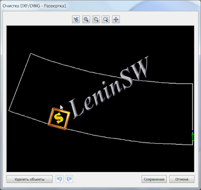
After the export is confirmed, the "DXF / DWG Clear" window opens, in this window you can delete unnecessary holes or other elements.
 |
| Cleaning |
If necessary, you can undo the changes. After cleaning, click "OK" and the dxf / dwg file is created in the location you specified.
Just sweep can be done without activating the flat state. To do this, select the unfoldable surface and save it as dxf. Solidworks add the "Sweep" before the name of the saved part. Further as in the previous case.
The other way is even simpler, right-click on the Sweep in the design tree and select "Export to DXF / DWG", further as described above.
And the easiest way, just save the part as dxf / dwg, the rest as in the previous cases.
And finally, the most complex and most (as it turned out) common option: saving from the drawing.
The bottom line is simple, you insert a sweep in the drawing sheet and save it in dxf / dwg. In addition to more actions, this option carries a very unpleasant feature: distortion of the scan scale. If the scale of the sheet coincides with the scale of the drawing view, there will be no scale distortion. In other cases, there are different options and this is the topic of a separate article. Therefore, I recommend exporting from the model, there will be no problems with scaling.

Комментариев нет:
Отправить комментарий