четверг, 15 февраля 2018 г.

How to Disable and Enable the Meltdown and Spectre Patches from Slowing Down Your PC

How to Disable the Meltdown and Spectre patch
  

The Windows patches for Meltdown and Spectre will slow your PC down. On a newer PC running Windows 10, you probably won’t notice. But, on a PC with an older processor—especially if it’s running Windows 7 or 8—you may see a noticeable slowdown.

You can also disable the protection in the registry yourself, if you like. Run the commands under “To disable this fix” on this Microsoft support page. Restart your PC after changing the registry settings. If you change your mind and want to re-enable the protection in the future, run the instructions under “To enable the fix” on the Microsoft web page.


You can use batch files to enable or disable the fix.
Download

  • disable_hotfix_Spectre_and_Meltdown.cmd
  • disable_hotfix_Spectre.cmd
  • enable_hotfix_Spectre_and_Meltdown.cmd
  • enable_hotfix_Spectre.cmd
Execute the required batch file and restart Windows.

суббота, 10 февраля 2018 г.

SolidWorks: Autotrace a Sketch Picture

Very useful function, but many do not know about its existence.

SOLIDWORKS AutoTrace
 AutoTrace sketch


Solidworks help
Sketch Picture includes the following capabilities:


  • Insert pictures (.bmp, .gif, .jpg, .jpeg, .tif, .tiff, .wmf, .png, .psd) on a sketch plane.
  • Use pictures as an underlay for creating 2D sketches.
  • Convert raster data to vector data using Autotrace.

A sketch picture is inserted with its (0, 0) coordinate at the sketch origin
If you insert a sketch picture of a .tiff file, the resolution is limited to 4096 x 4096. Files that exceed this limit are cut in half until both dimensions meet the limit. For example, if you insert a .tiff file that is 5000 x 3000, the file is reduced to 2500 x 1500.


>
Autotrace is an add-in that allows you to trace and convert images such as .jpegs and .bitmaps into sketch geometry. This add-in works best with high-contrast images.
  • Source image should be hi-resolution, with a minimum of 300dpi. 
  • Line art should be pen on paper, with precise contours and high contrast.
  • Colors should be as uniform as possible within the area you select.
A sketch picture is inserted with its (0, 0) coordinate at the sketch origin:

The second page of the Sketch Picture PropertyManager is only available if Autotrace is enabled as an add-in. Click Tools > Add-Ins and select Autotrace in the dialog box.

Compatibility with Autotrace
  • You can use still image formats such as .bmp, .gif, or .jpg, but not animated formats such as animated gif or .avi files. 
  • You can apply Autotrace to part or assembly files (*.sldprt and *.sldasm), but not to drawing files (*.slddrw).


четверг, 1 февраля 2018 г.

Performance of SOLIDWORKS after applying the patch Specter and Meltdown


DS SOLIDWORKS is performing extensive testing in an effort to determine the potential impact of any solutions that are issued to mitigate the Spectre and Meltdown vulnerabilities.
The SOLIDWORKS Knowledgebase solution S-074167 discusses the potential effect on performance upon systems that have employed the Microsoft® Windows® Update security patch released on January 9th, 2018 that was intended to address the Spectre and Meltdown vulnerabilities.

DS SOLIDWORKS intends to report the results of their ongoing tests at SOLIDWORKS World (Feb 4th – 7th 2018). The report will likely be relayed to reseller staff and further updates can be expected by our customers during the second week in February.

SOLIDWORKS Knowledgebase solution S-074167

SOLUTION ID: S-074167

  • QUESTION: Why does my computer with an Intel® processor perform slower after installing a Windows® Update?
  • ANSWER: A critical security fault was identified with all Intel® x86 and x64 processors. The security fault was fixed by a Microsoft® Windows® Update security patch released on January 9th, 2018.For information about this issue, follow these links:


You should also review the following Microsoft article:
Windows 10 update kb4056892

среда, 31 января 2018 г.

Running Feature Paint in SOLIDworks

Rarely used functional - Running Feature Paint. Beginners do not know, others forget. Feature Paint allows you to copy feature parameters from one feature to others. 


SOLIDWORKS Help

Feature Paint allows you to copy feature parameters from one feature to others that you select. For instance, you can select a boss-extrude from one part and apply its parameters (such as depth) to another boss-extrude on a different part.


You can also select two different features and apply feature parameters. For example, select a sweep feature to apply its parameters (such as the texture and transparency properties) to a dome feature.


Sheet metal features are supported. 
Parameters you can copy include:
  • depth 
  • color 
  • texture 
  • optical properties (including ambience and specularity)
Limitations:
  • Unsupported sheet metal features: bend, fold, unfold, and welded corner. 
  • If the source feature does not have texture but the target feature does, the target feature retains its texture properties. 
  • Reference geometry entities cannot be painted from one feature to another. For example, an end condition of Up To Surface that references a surface cannot be painted.
To run Feature Paint:


    Click Feature Paint (Tools toolbar) or Tools, Feature Paint.

    The Feature Paint Task Pane opens.

    In the graphics area, select the feature whose parameters you want to copy.

    <feature name>@<part name>.sldprt appears in the Copy properties from box.

    In the graphics area, select one or more features to which you want the parameters applied. You can select a feature in the current part, or select a feature from a part in another open window.

    1.<feature name>@<part name>.sldprt appears in the Paste properties to box.

    The Feature properties box lists the following feature parameter information:
  • Parameter. The feature property to be copied. 
  • Copy from 
  • Paste to
    NOTES: 
  • If there are no attributes listed in the Feature properties box, then no attributes are available to copy.
  1. Select Paste appearance properties to apply appearance properties (color, texture, and so on) only. 
  2. Click Apply. 
  3. The new attributes are updated immediately. 
  4. Click Close.

See this video


    воскресенье, 21 января 2018 г.

    Projected View

    Not everyone knows that if you click "Ctrl" when inserted projection views, the view is automatically break alignment.
    In general, there is a lot of additional functionality in the Solidworks when you press "Ctrl", "Alt" and "Shift". 


    среда, 22 ноября 2017 г.

    Save and Restore User Settings Solidworks


    When reinstalling the system or Solidworks, you want to save your personal settings, in order to restore them later. Also it is convenient when transferring the Solidworks settings (toolbars, menus, hot keys) to another computer. The utility "SolidWorks Copy Settings Wizard", which is part of SolidWorks, will help us in this. The utility is on the path

    "C:\Program Files\SolidWorks\SolidWorks\setup\i386\copyoptwiz.exe"

    or in the "Start" menu - "All Programs"
    Solidworks - утилита копирования и воcстановления настроек в Windows
    Solidworks 2012 - Copy Settings Wizard.


    In versions of Solidworks 2015 and later, you can run the utility directly from Solidworks.


    Launch the "Solidworks Copy Settings Wizard".
    Solidworks - The startup window of the utility for copying and restoring settings in the Solidworks menu


    Choose Save Settings


    Choose which settings you want to save and the location of the settings file. Done.


    Restoring settings is done in a similar way.


    Click "Restore Settings" - "Next"


    We show the settings file and choose which settings to import.
    Pay attention to the possibility of importing settings settings in different versions of Solidworks. The screenshot shows the restoration of the Solidworks 2016 settings using the utility from the Solidworks 2017 suite.


    Just in case, put a check mark "Create backup copy" - "Done".


    All. You can run Solidworks and enjoy the familiar interface.
    If you tick the "Backup current settings" checkbox, the utility will save the file starting with the words "backup" before restoring the setting,
    Solidworks - Файлы настроек Solidworks


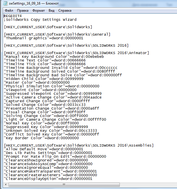
    You can restore Solidworks 2017 settings to Solidworks 2016 or earlier. Remember to change the location of toolbars in newer versions.

    A file with saved settings is the most ordinary reg-file only with the extension "sldreg"


    Thus, you can import the Solidworks settings even without the "Solidworks Copy Settings Wizard" utility, by simply entering data into the registry. This can be done by double clicking on the file and confirming the data entry in the registry, or through the Windows regedit utility.

    Of course, you can restore settings to other Solidworks versions via the "Solidoworks Settings Copy Wizard", but if you want, you can change the year in the reg file to the required ones and also make the settings in other versions. For example, opening a file with a notebook and making a replacement for "2016" for "2015" we get the file of the settings Solidworks 2015.

    Attention !!! When migrating from Solidworks 2008 or lower to Solidworks 2009 or higher, you should note that the default installation path has changed:

    "C:\Program Files\SolidWorks\SolidWorks" - Solidworks 2008 or lower

    "C:\Program Files\SolidWorks Corp\SolidWorks" -  Solidworks 2009 or higher.

    понедельник, 13 ноября 2017 г.

    The share sketch in Solidworks

    There is one interesting feature in Solidworks that I did not find in the Solidworks help or was looking badly :). Use one sketch in different elements. To do this, select the sketch by clicking the left mouse button on the sketch, (first open it in the tree) and click on the desired element: draw, cut, etc. After that, enter the parameters and confirm. As a result, you will get an element that is created with a sketch from another element. The icon for such a sketch, used in several elements, looks like a sketch with the palm opened under it, similar to the common folders in Windows.
    Solidworks общий эскиз


    You can use sketches of different elements in other elements repeatedly.
    For example, we'll make a figurine on the panel, we'll simulate it the way it is done in the production: we make the workpiece and then milling it along the contour.
    Solidworks общий эскиз

    Use the "Swept Cut"


    Solidworks общий эскиз - заготовка

    Specify the profile

    Solidworks общий эскиз

    and the trajectory of the cutout

    Solidworks общий эскиз

    Repeat our actions for the other side of the workpiece

    Solidworks общий эскиз


    Solidworks общий эскиз


    As a result, we received a parametric panel.


    Solidworks общий эскиз в параметрической филенке


    See this video.


    test

    data-matched-content-ui-type="text" data-matched-content-rows-num="2" data-matched-content-columns-num="4"

    test3

    data-matched-content-rows-num="2" data-matched-content-columns-num="2" data-matched-content-ui-type="image_stacked" data-ad-format="autorelaxed" data-matched-content-rows-num="4" data-matched-content-columns-num="2" data-matched-content-ui-type="image_stacked" data-ad-format="autorelaxed"